

Ok, lets get more clear what is Knitic all about!
The previous post was about making PCBs for Knitic. Why that? Because the idea is to control the knitting machine directly via Arduino and Processing.
So we have opened up the machine and studies the mechanics and electronics of it. We left following useful components for us:
1. two encoders that determine position and direction of cartage. To tell more, it is not so easy task
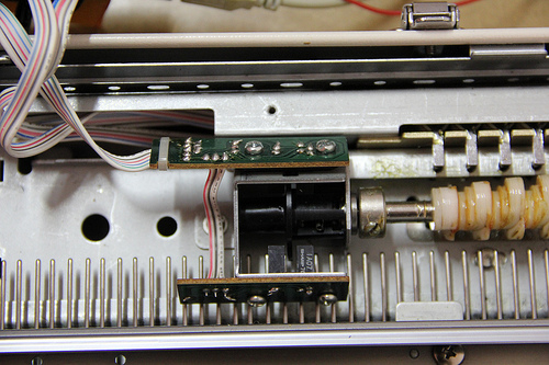
Components:
1x IA07 SHARP 78
2x another sharp
3 resistors
2. right end-of-line sensors:
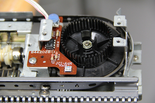
components:
chip: NEC Japan C358C 740C (low power dual operational amplifier), datasheet.
2 resistors of 2.2K
2 resistors of 5K
1 trimmer
1 hall effect sensor -> Melexis 90217
3. left end-of-line sensors:
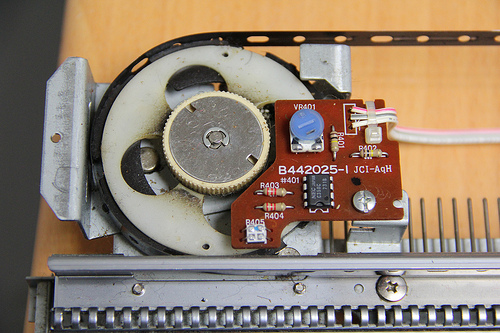
same components as the right end-of-line sensor
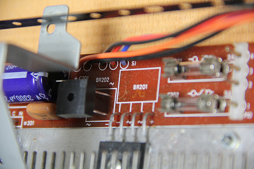
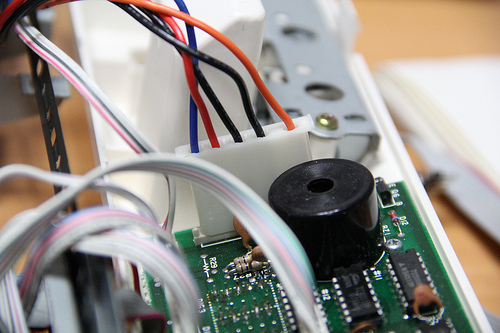
4. Circuit in the middle of knitting machine
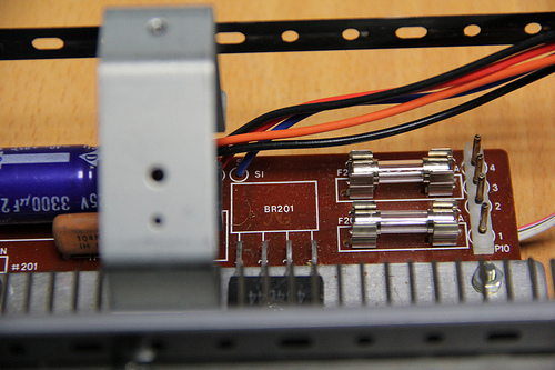
BR201 is T 7 1 4B4B44 component
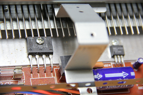
2 fuses: F201 2A and F202 5A
AC to DC transformer marked as BR202 on the board
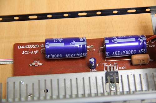
capacitor 104K IH I:
2 capacitors of 3300uF 25V
1 capacitor of 47uF 10V
1 resistor of 2.2K
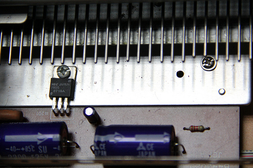
1 transistor NEC Japan 7805 8716A (voltage regulator), datasheet
IN, GND, output 5V
datasheet
5. 16 solenoids, which are pulling out needles according to the pattern:
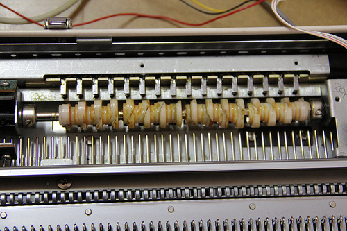
16 solenoids of 12V
+ is interconnected; GND goes to transistor arrays (into pin-heads).
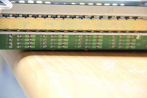
10-pin-head
|8|7|6|5|4|3|2|1|+|+|
these are solenoid numbers according to the pin connections from left to right
8-pin-head
|16|15|14|13|12|11|10|9|
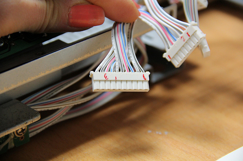
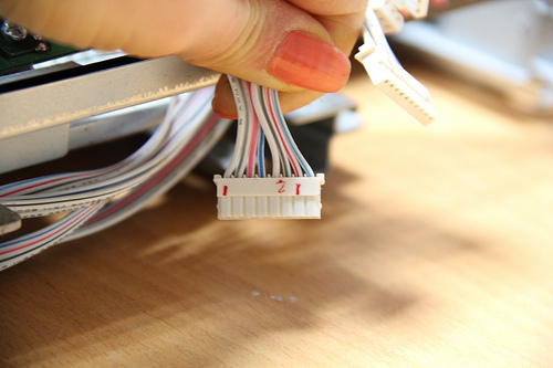
6.POWER
|12V|5V|GND|GND|16V|
16V goes to solenoids, 5V to end-of-line sensors and encoders
And here Mar sweating on the code of Knitic:
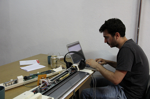
As you see from the photo, the original brain of knitting machine has been abandoned and we are controlling machine directly from a computer.